INFLATABLE
BOATS
|
|
Remember safety is your own responsibility.
Altering boats will void manufacturer's warranties. You must register
the vessel prior to installing any type of motor. Wear PFD at all
times! Check with your local laws and customs before doing any work.
I
purchased this pontoon boat on eBay several years ago for $125 plus $25
S&H. I was quite excited when I received the package a couple of
days later. I drove down to a local pond and inflated it put all my
gear inside and cast off. My initial excitement immediately waned. The
boat sagged the transom buckled, rowing was difficult and when I turned
on the trolling motor I had to hold on to it to keep it from ripping
the back end off the boat.
|
I
realized the part of the problem was the craft did not have a solid
bottom, passenger and gear warped the boat's sleek lines. I decided to
fix the problem and build this into the boat it was meant to be.
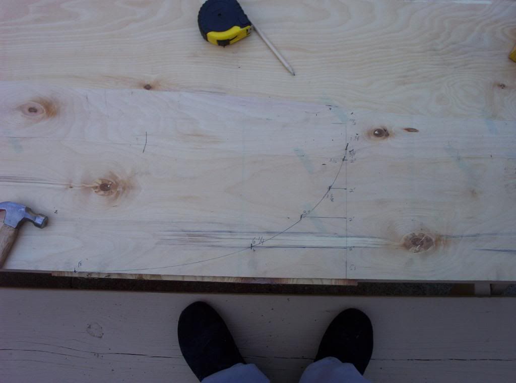
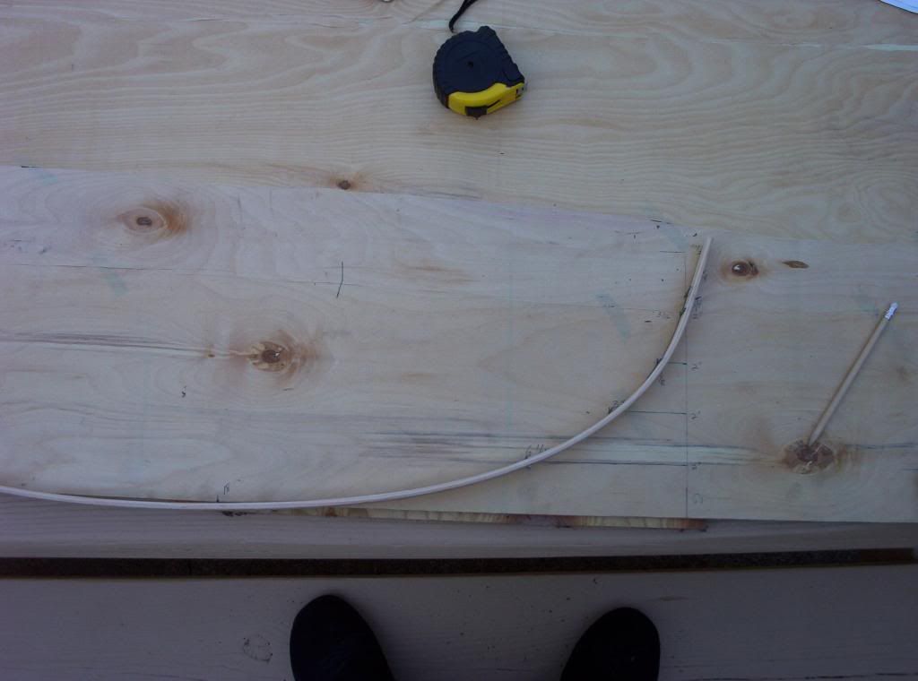
I
made templates of the boat's bottom by tracing the outline onto craft
paper. Next I cut 1/4 inch plywood using the paper template as a guide.
I rounded off all corners to prevent any punctures to the boat.
When
I tried to slip the sheet of plywood inside the boat it seemed as
though the tight fit might tear the canvas floor. This was quickly
solved by cutting the sheet where it starts to narrow, thereby
facilitating insertion.
|
 Once
again I rounded off all corners to prevent any damage to the canvas.
The two sections of plywood were joined together using aluminum
channel. The arrangement worked very well. Once
again I rounded off all corners to prevent any damage to the canvas.
The two sections of plywood were joined together using aluminum
channel. The arrangement worked very well.
The
Boat came with a wooden transom. I since replaced the original with the
same stock used to build the floor.
I
also built two L shaped brackets of thick aluminum stock to reinforce
the transom. After a few uses it became clear they had to be replaced
by stronger material.. |
Before
taking the boat out I sanded the plywood sections and coated them with
polyurethane. I have since given several coats of the stuff.
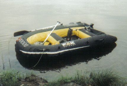
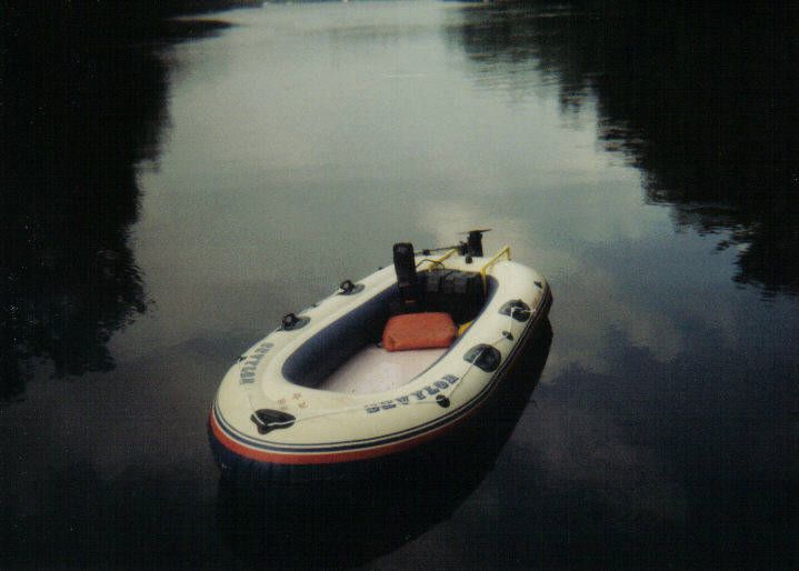
The
picture on the left shows the end result. The craft retained it's sleek
lines even when carrying two passengers and equipment. I also used a
2.2 HP gas motor on it an could probably use an even bigger motor
safely.
I
done more experiments to improve performance of the vessel such as
adhering an sock tube to the bottom of the plywood sheets. When
inflated the canvas floor beneath it will assume a V shape giving the
craft greater stability and a noticeable difference in speed.
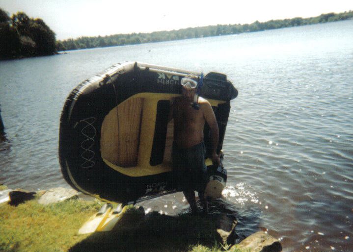
The
craft is so light I carry it in and out of the water with one hand
while my free hand carries the outboard motor.
After
several uses the aluminum brackets used to reinforce the transom
started to loose their rigidity. I replaced them with steel heavy duty
shelving brackets from Home Depot. They have worked well so far
|
|
|
Using
the lessons I learned from the previous project I decided to tackle my
Sevylor boat.
Originally
these boats were intended to be powered by low thrust motors sold by
Sevylor. Unfortunately the company stopped selling both the motor and
the transom kit.
I
did find one boat for sale with a transom mount but was disappointed
with it. What a piece of junk. It was too flimsy and the design
actually hindered performance. the rods extended under the boat
creating drag. Anyone who has ever seen the transom mounts sold by the
makers of inflatable boats will agree with me on this.
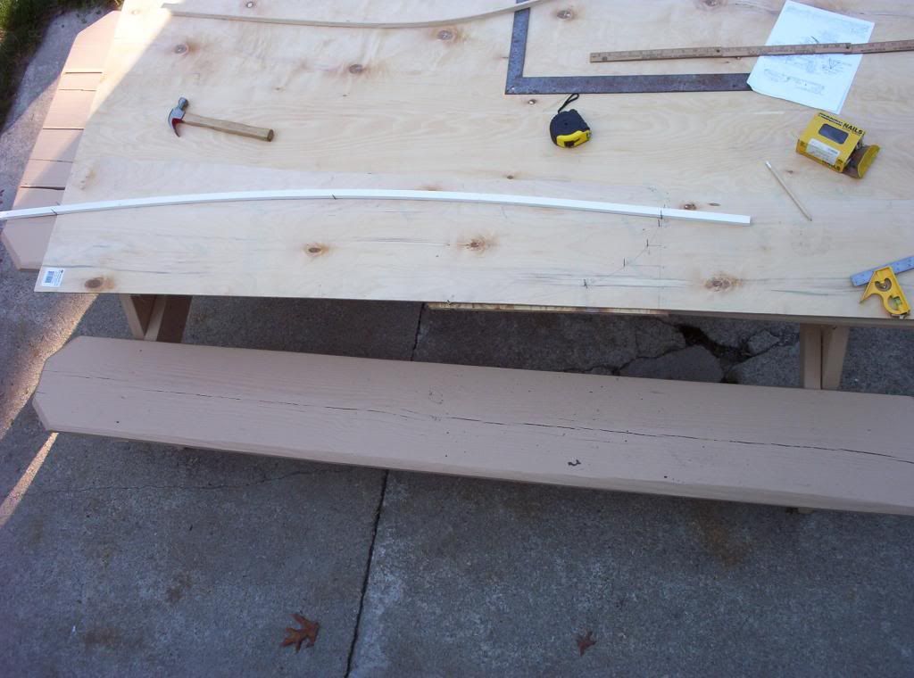
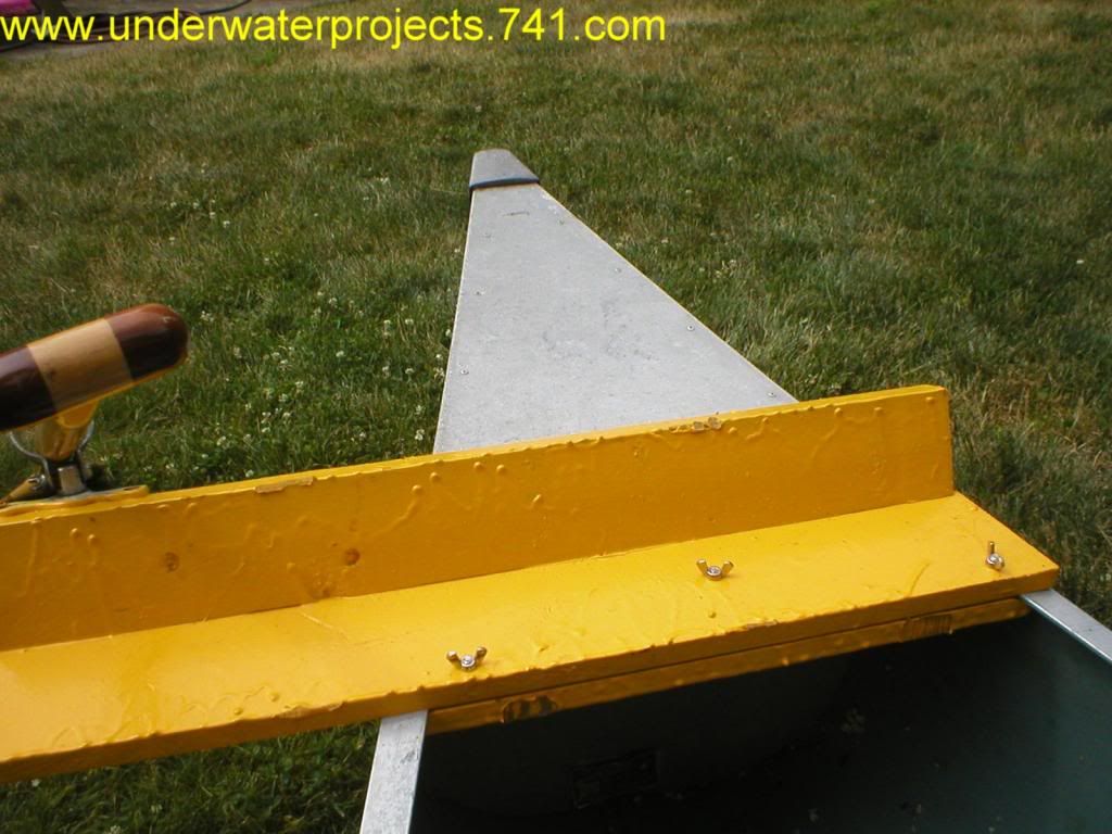
 My
own transom mount was built of simple to make PVC pipe with a 1X4 "
length of wood mounted horizontally. The pipe only reach down to the
water line and should not create any drag. My
own transom mount was built of simple to make PVC pipe with a 1X4 "
length of wood mounted horizontally. The pipe only reach down to the
water line and should not create any drag.
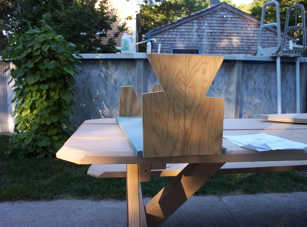
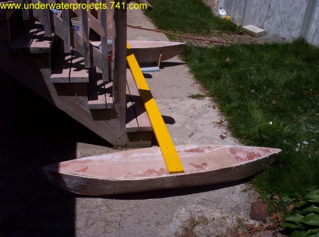
The
mount loops over the air chamber and attaches to a floor which was
built of pink construction foam layered in fiberglass. Make sure you
use epoxy resin when making foam core projects, other types will melt
foam ruining your project.
The
battery case was attached to the PVC tubing to provide added security
to the design. I was afraid the foam core did not provide a solid
foundation to the mount. The weight of the battery insured the mount
did not detach from the floor.
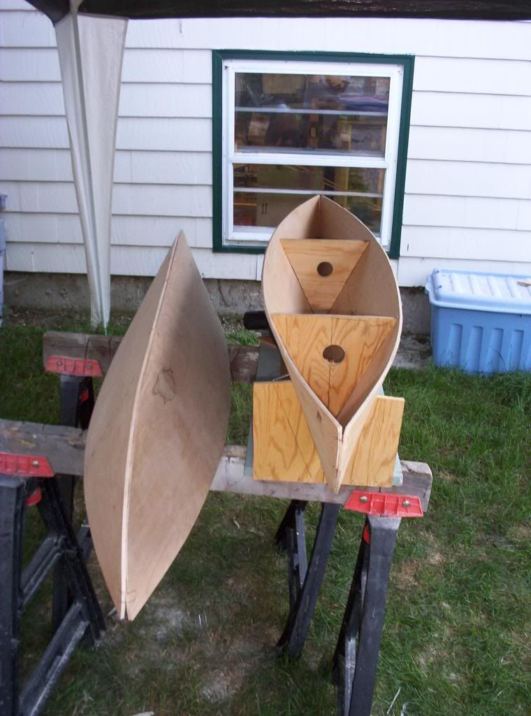
The
foam core floor is installed prior to inflating the craft. When
inflated the air chambers hold the floor in place.
The
design worked very well. The only drawback was con fort. The Sevylor's
inflatable floor was now beneath the hard foam core.
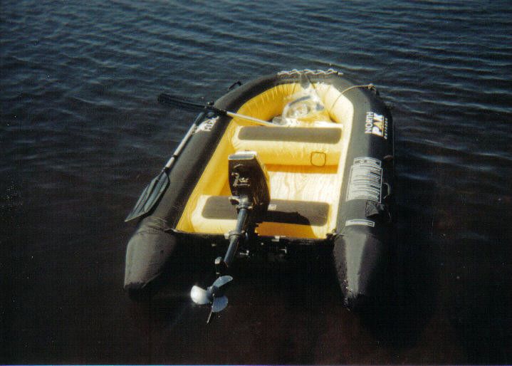
Instead
of the wimpy Sevylor motor I used a Stealth 25 lb thrust motor.
I
fell in the water once and got back on the boat without much trouble,
I'm sure the same would not have been said had I not installed the
floor. Just imagine trying to get back onto a boat that bends as you
are trying to climb back in. I was wearing my PFD. Without it I
probably would have panicked.
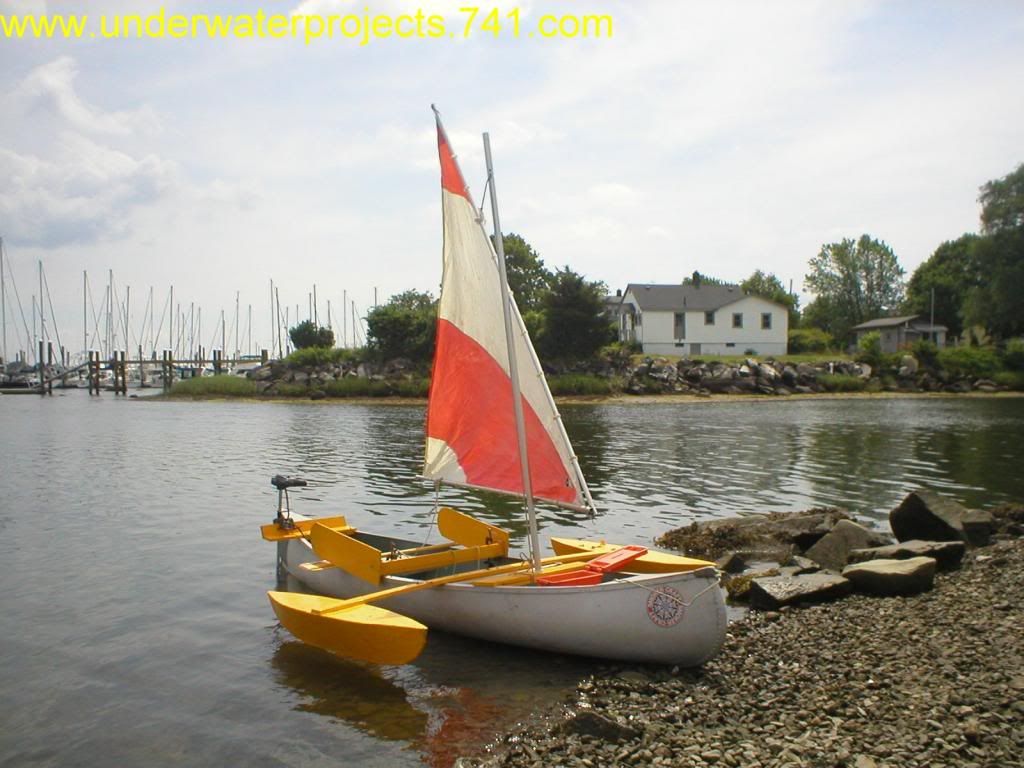
Look
how sleek and rigid the craft looks!
These
boats are so versatile, they go where no other boats will. Secluded
coves, narrow channels, shallow ponds... Are all accessible with these
very inexpensive craft.
|
SAILING CANOE
|
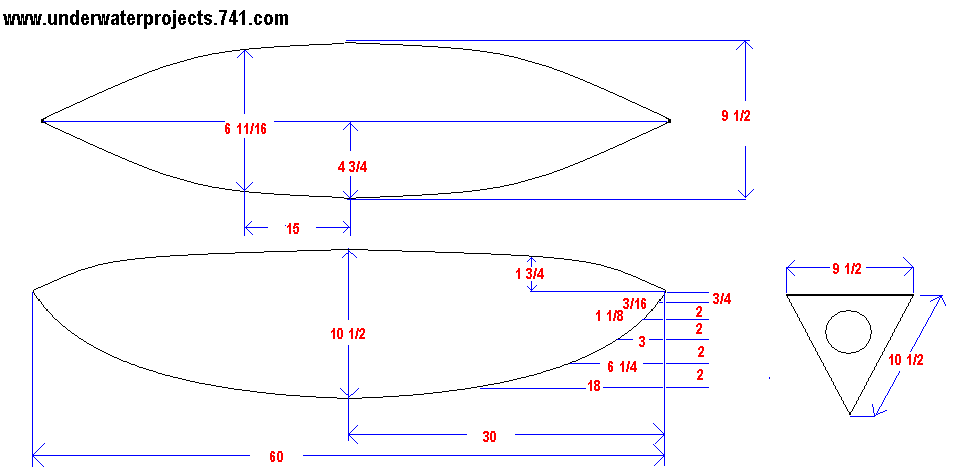
RIGHT CLICK ON THE PICTURE ABOVE AND DOWNLOAD IT THEN PRINT IT OUT
|
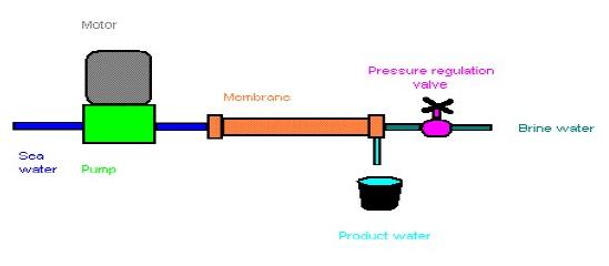
WATERMAKER PLANS
|
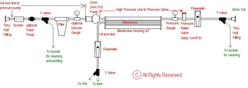
The
diagram shown is a schematic. The parts are all commonplace and easy to
obtain from most marine hardware suppliers. The diagram is self
explanatory but the following is a quick run through of the component
parts:
1.The
thru hull fitting should ideally be a dedicated three quarter inch
fitting.
2.A
sea strainer or screen connected to the hull fitting by a three quarter
inch line, which will continue on to the pressure pump.
3.After
the screen, which is intended to remove solids such as seaweed, is an
optional feed pump, whose purpose is to ensure that airlocks do not
occur in the system.
4.Following
the feed pump is a Y-valve with a free tail, which is used for cleaning
and pickling the system. This tail usually has a small filter on the
bottom, and is inserted in a bucket with the pickling solution.
5.This
is followed by a filter which should be a 20-30 micron filter. Some
filter housings have a by-pass valve which allows you to eliminate the
Y-valve and have the cleaning and pickling pipe going to this system
directly.
6.The
filter is followed by an optional vacuum gauge, followed by
7.A
1,500 psi high pressure pump, not 2-3000 psi as stated in the diagram,
which will be run at 800 psi and can be either electrically or engine
driven. CAT pumps are suitable for this purpose.
8.The
membrane and pressure vessel, which in this case is a 42 inch long
system, is connected to the pump by a high pressure line, which
continues to the pressure valve
9.From
the membrane, a quarter inch plastic line goes through a flow meter to
a Y-valve which can be connected to the water tank for drinkable water,
and optionally, to the sink.
10.From
the other side of the membrane and pressure vessel connected by a high
pressure line is a pressure gauge to 1,000 psi, followed by a
11.Pressure
valve with optional bypass at 1,000psi.
12.From
this valve, a quarter inch line continues through a flow meter and a
13.Y-valve
which will discharge overboard, or to the cleaning bucket.
It
is quite a simple unit to build, and with proper maintenance should
give 100 litres per hour for many years,
|
FOR FURTHER STUDY
CHECK OUT
MY EBOOK REVERSE OSMOSIS
Watermaker
Plans
Watermaker Page
|
|