Build
Your Own R/C
Submarine and ROV
|
| INTRODUCTION: FREE ROV PLANS
This
project is designed for the
beginner. Anyone can build this in his own basement, garage or living
room. Even if you never built an R/C model before you can tackle this
one with confidence.
The
hull can be adapted to
incorporate a wide variety of components. Dimensions are left out
intensionally, purchase all your items and don't start cutting the hull
sections until you've assembled the internal framework.
TECHNICAL
DATA:
Dimension: 15-16"/ 38-40 cm
long, 9.5"/ 24 cm
wide, 7"/ 18cm high
Weight: ca 9 Lb/ 4-5 kg
Range: 40 minutes continous operation
Test Dive: 6 feet/ 1.70 m. Can be
extended using an umbilical.
HULL
PARTS LIST
The
type of
drain pipe used isn't sold by Home Depot or Lowes. You can find these
at industrial suppliersl Look in your phone book for a seller near
you. You can easily substitute PVC for ABS which is available at
the two retailers mentioned. Stick to thinner pipe typically used for
French drains, the thicker stock intended for pressure applications is
costlier, harder to machine and the inner dimensions may be too
restrictive.
|
| |
Shell:
2 ABS, PVC Rain Pipe End Caps 4"/ 100mm
1
ABS, PVC
Rain PipeT-junction 4"/ 100mm with gasket and screw cap
1 ,
ABS, PVC
Rain Pipe double junction 4"/ 100 mm
1 half sphere Christmas ball
2 Rain Pipe wall mounting ring 4"/ 100 mm
4 Rain Pipe wall mounting ring 2"/ 50 mm
Tube of Aquarium Silicone
2 Air compressor male-male connectors 1/4"/ 6mm
Bolts & nuts |
Motors:
4
ABS, PVC
Rain Pipe end caps 2"/ 50mm
2
ABS, PVC
Rain Pipe 2"/ 50mm
2
ABS, PVC
Rain Pipe double junction tube 2"/ 50mm
2 half sphere Christmas ball 2"/ 50mm
4 Air compressor male-male connector 2"/ 6mm
1 aluminium Channel/ U shape bar
2 motor Grupner 400 7.2 V
2 Electric cables 40"/ 100cm
2 Shaft with propeller
2 couples and transmission for motor to propeller shaft |
|
Electronics:
1 RC receiver (3 channel) 27MHz
2 speed control (regulators) Navi Type or similar
1 Battery Pack 7.2 V 2000mA
Cables
Plugs, nuts, bi-adhesive 3M |
Blow tank: (option):
1 Servo 8Kg/cm or more
1 Syringe Veterinary Type
Plastic Tube
Aluminium channel, U shape bars |
Frame:
1 screw type bar, cut in 4 pieces
1 aluminium channel, U shape bar
4 plywood circles 3 1/8"/ 80 mm
Bolts & nuts |
Fittings & others:
4.40 lb/ 2 KGs ca. Lead for trimming
1 Spray Paint Black
Stickers |
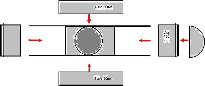
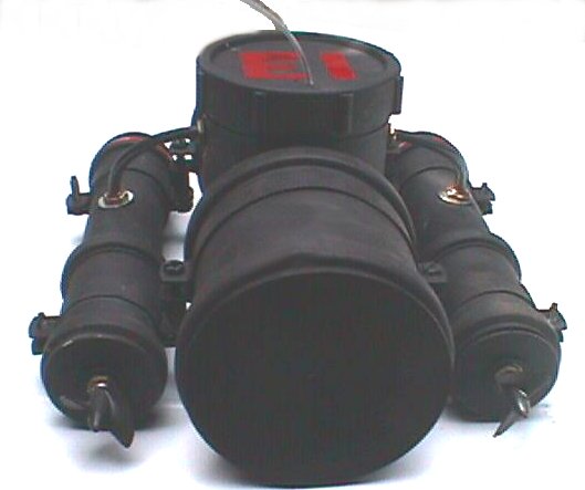
SHELL
The shell can be constructed of a variety of materials, including PVC
and ABS. Aside from the bonding agents recommended by manufacturers you
can also use silicone and acrylic adhesive which will bond different
types of plastics together including acrylics, it even bonds plastics
to glass.
The hull is binded to the motors by strap used to fasten pipes to walls
and ceilings. In case these are hard to find substitute them for
aluminum strap, bend them over the hull sections and shape them using a
pair of pliers or vise grips.
Holes are drilled for cables. This too is not terribly important to the
design, but symetry is critical as it may affect control and stability
of the sub.
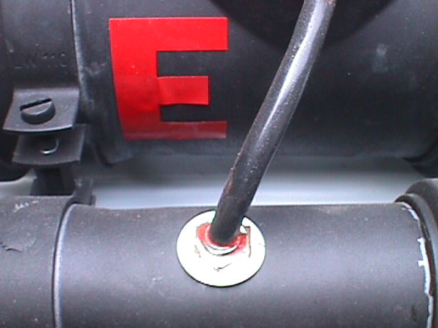
Air line fittings used for compressed air tools were used for this,
with gaskets to prevent any leaks.
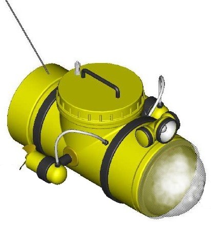
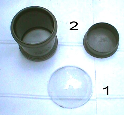
A clear plastic hemisphere from a Christmas ornament was used to
streamline the forward part shell, this greatly improves the handling
of the sub. You may also install a second in the trailing side. Should
you want to convert this sub to an ROV an acrylic dome is recommended.
See section of suppliers at the end of this ebook. You may also create
your own plastic bubble by making a frame with the acylic sandwiched
between sections, a hole is cut on top roughly the shape of your
intended bubble. This is then heated in an oven to make the acrylic
supple and copmressed air is pumped in expanding the flat material into
a bubble.
The sub is then sanded and painted with automotive paint, color is
optional.
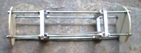 |
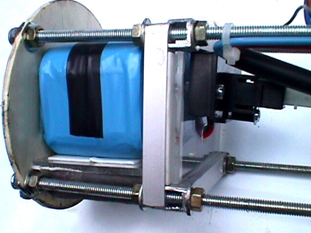
The
frame is built of 4
threaded bars with nuts holding all the components together. A bit time
consuming but highly adaptable to a wide variety of different R/C
brands.
|

|
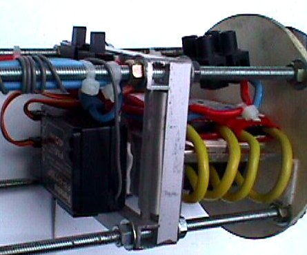
Bases and supports for fittings are
made with
transparent Lexan. The picture illustrate the result. |
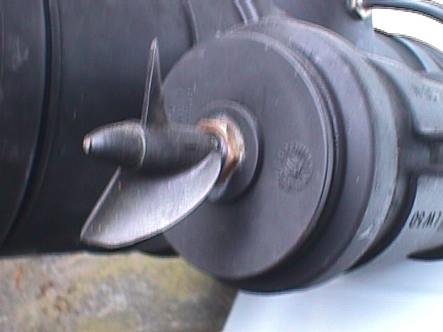
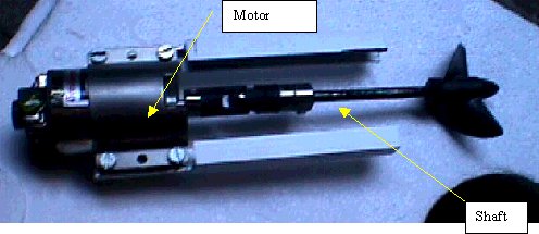
The
two motors are very
simple to make. A Grupner 400 with a coupling shaf/ stuffing box combo.
Almost any motor up to12 volt will do but there will be some
torque lost
when using lower voltage power supply.
The system is framed in aluminium bracket and a cable connects it to
the
central shell.
Grease is used for watertight seal.
|
|
|
|
 |
|
|
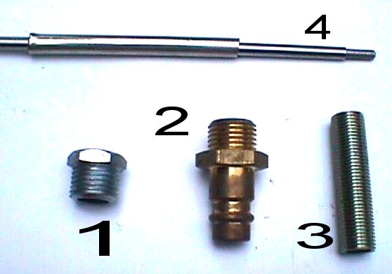
Details
of parts used for
the motor assembly
|
ELECTRONICS
|
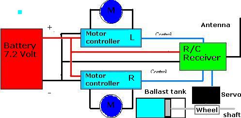
| The
Electronic/electrical
system is simple. If you do not install the Blow Tank you can use a two
channel R/C Transmitter. |
|
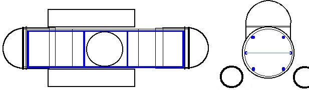
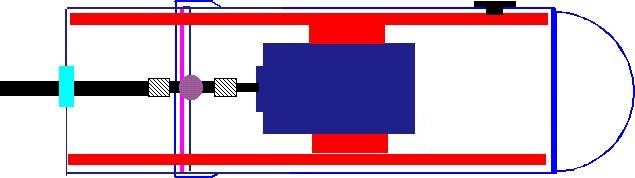
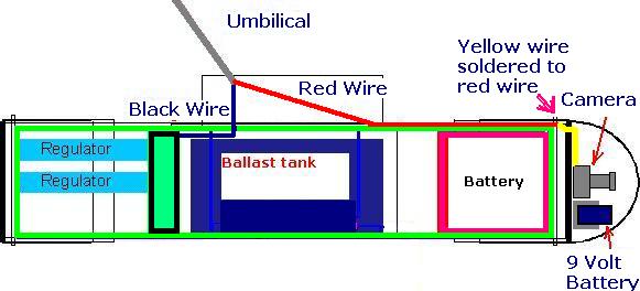
The
diagram on the right
shows the principle circuit: The
regulators (speed control) are also a "battery eliminator" system for
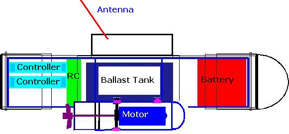
the receiver. The set up inside the shell is on the frame.
Battery was mounted in front and all the other electronics in the back
leaving space in the middle for the ballast tank (optional). Look at
other
pictures...
|
|
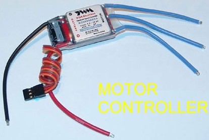
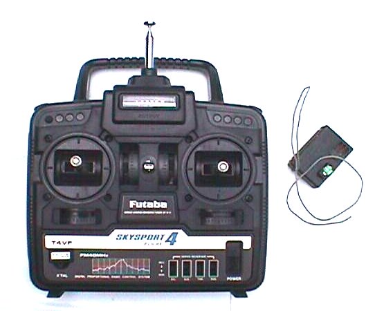
There
are many brands of
motor controls. I recommend you purchase one like the one on the left.
These units plug right in to your receiver, and all you need do is
solder or connect the motor connections, and power source.
For less than $20 you can purchase one on eBay. Make sure there are
english instructions with it.
|
|
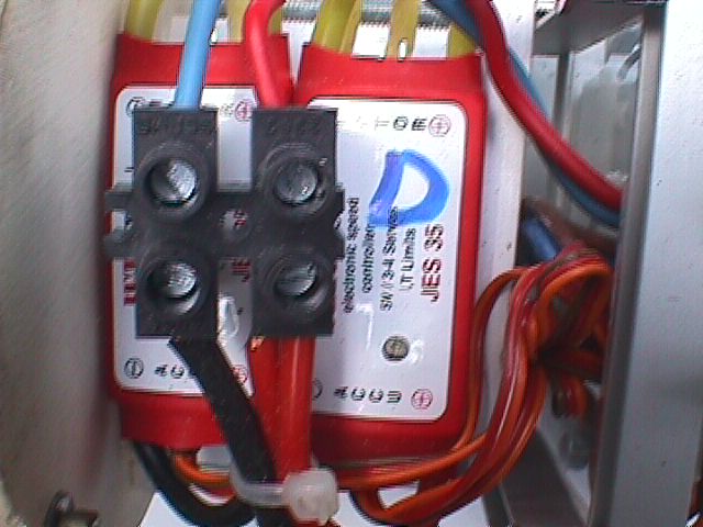
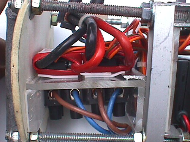
Your
Sub should look like
this.
If you are not confident soldering all the electrical components
together, use a bus terminal like the one in the picture below.
|
|
|
BALLAST TANK
|
A
simple way to get the
sub to dive is to trim your sub so that the front of the vehicle sinks
a little deeper than the back end. When power is applied the sub will
slip beneath beneath the waves, and to surface power is cut off to the
motors.
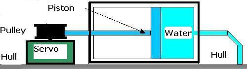
If you want to better
control the sub a Blow Tank is needed. In this case a 3 Channel RC
controls the system. The principle is simple. A strong servo (8-10
Kg/cm) move back and
forward a piston that sucks water inside the sub and it goes down! See
drawing below.
|
 |
|
 |
|
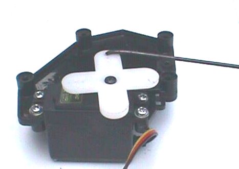
To
build your ballast tank
remove the actuator from the servo, this is the cross shaped part in
the picture above, yours may be different. Next insert a gear to drive
the shaft which is attached to the piston.
The piston is used by plumbers to unclog sinks. They are sometimes sold
as 'Kinetic Drain Openers' or 'Suction And Force Plungers' and there
may be other designations. |
A veternary syringe will also wor, and with
some enginuity a pump used to extract resin from cans will work, with
some modifications. The spring and ball valves must be removed. This
will allow the piston t o move freely
and allow the water to move in both directions.
A third alvernative to all of this is to purchase a ballast system
already made and tested from the supplier's list at the end of this
ebook.
An untested method would be to sling a weight between two pulleys. The
string holdind up the weight loops over both pulleys like a clothes
line,with the servo driving one of the pulleys. As the weight moves
forward the front end will sink lower than the back, making the sub
submerge when the motors are turning, the opposite happens when the
weight is moved rearward. This way you can travel at full speed when
surfacing.
|
|
TRIMMING:
Before deep test run you have to trim
your boat.
Add some lead to balance the sub. If
you do not
use the ballast tank, the sub has to be a bit heavy in front in
order to use the motor to go down. The ship in this case should
be a
bit "Positive".
If you are using the ballast tank the
ship
should be carefully balanced and neutrally bouyant or
bit positive.
OPERATION:
Without the ballast tank just use the two
motors to
submerge and no power to surface.
Use alternatively one or the other to turn
around. That’s
all.
|
 |
|
 |
|
 |
In the sub version
the hemisphere was painted and two holes were drilled on opposite
sides. The plastic bubble was mounted so the holes were facing top and
bottom. This let's the water in and the air out allowing the sub to
submerge.
If you are planning to build an ROV do not drill holes in the plastic
dome.
|
 |

|
 |
|
 |
|
 |
|
 |
|
|
|
A
Cheaper
Alternative
|
The next generation model
submarine. There's no
ballast tanks, frame or motors to assemble. By eliminating the ballast
tank we've made the sub much smaller without the need for frame work.
All componenents were held togther using wire ties. Instead of motors
driving propellers we employed submersible pumps, these are already
waterproof.
This
sub's dimensions are similar to the above example, but much
slimmer. Without the ballast tank this craft relies solely on impulse
to dive.
Building An ROV
|
|
Underwater Radio
Many have thought of using radio equipment underwater. I've often been
asked of the possibility to adapt wireless devices to underwater use.
Unfortunately it's not feasible to use most wireless gadgets
underwater. The conductivity of the Sea is sufficiently high (1.6 mho
per foot) to diminish a radio wave at very short distances.
For example a metal detector operating in the one meter range or less
loses 99.9% of its radiated energy within four inches of water.
As wavelengths increase (lower frequencies) the
performance improves. 1000 meter waves will travel 5 feet loosing 99.9%
in the process, and 10,000 meter will travel 33 feet, making it
practical for rudimentary communication. A quarter wave antenna used to
project such a long wave needs to be a mile and a half long.
Submarine's radio use long cables attached to a Para vane which
maintains the cable at a desired depth to communicate with their base.
Use of wireless devices underwater is impractical, our model sub works
in fresh water at shallow depths such as in pools because of its low
frequency wavelength. Video transmission occurs in the narrow bands and
reception would be cease once the sub dove.To overcome this ROV
designers incorporate an umbilical, either a copper wire or in some
high tech models a fiber optic cable is used to control the ROV and
recieve telemetry from the vehicle.
The following are excerpts from my underwater video camera project.
|
|
Starter Project
This is perhaps the
easiest, and least expensive camera projects to
build. It involves encasing a spy camera in a polymer inside a clear
plastic box, that doubles as a mold, lens and housing. |
>____________
|,----------.|
||
||
/-------< ground
||
||
/
||
||
/
|`----------'|
//------< + 12 volts
|o .... [###]| RCA Jack //
|____________|->--------,
// Alligator Clips
\/ connect direct to
Monitor
0 battery
0
)`. )`. )`. )`. 0`. )`.
)`. )`. )`.
-'
`-' `-' `-' `-'8 `-'
`-' `-' `-' `-
8
8
8
8
8
8
Fish
8
8
\\\\ 8
.-' `-. 8
\
.-'
'. 8
;\..-'
'-. 8
}
.. {{
(*) / 8
;/
~-.
_\ 8
/
~-. .;;'~ 8
///~~''~ 8
8
+-------+ 8
/ /| 8
,''''''`:
|8
| | |
|
CAM | /
| |/
'`'''''''
|
Materials Needed
- One camera. Try
getting
supercircuits.com PC
166XS, or these less expensive models; PC 33XP, PC 300XS both $11.95;
PC 302XP, PC 302XS both are good quality CCD units and a bit more
expensive.
- 50 feet of video
cable with RCA
connectors,
they vary, get one that matches your unit. Supercircuits' Model #
EXT-POW-50 matches PC 166XS camera. An alternative is to purchase the
cable on your own and solder the plugs yourself. Shielded cable can be
purchased at Home Depot, and the plugs are available at Radio Shack,
both at very reasonable prices. This
type of cable is too stiff for our ROV, it will hinder the sub from
maneuvering freely. Communication cable is
recomended for the Sub project. You need 2 conductor if you intend to
use a 9 Volt supply and 4 if a 12 volt surface supply is used. The ones
I use are of the General Cable brand.
- A clear plastic box
at least 1 1/2
"(3.8 cm) X
1 1/2" X 1 1/2". A suitable box is a display case used to house
expensive collectibles such as Beenie Babies, rare Matchbox cars... Try
hobby shops, or arts and crafts stores.
- One monitor, or any
TV with RCA
receptacles.
Due to the popularity of video games these are common on many portable
DVD players. If you have a portable TV with a coaxial cable connection
RFU unit costing $7 can be adapted to it. If you choose the latter you
don't need RCA plug. More on this later.
- A 12 volt battery.
|
Supplies
- One 8 oz (228 ml)
epoxy compound or
polyurethane compound kit. Found at hobby shops, hardware stores, or
fiberglass supply outlets.
- One small tube of
clear silicone
sealant.
- Heat shrinking
tubing.
- Roll of electrical
tape.
- Pair of latex
gloves.
- Dozen toothpicks.
- Old newspapers.
- Rags or paper
towels, and cleaning
solution.
Fabrication
Always test your camera prior to
casing it in
polymer. Read the manufacturer's instructions and follow the
guidelines. Not all spy cameras will work off a 12 volt power supply,
some are rated for 9 volts. Next read the section on adjusting the
focus on your camera model. you want the focus to be sharp when objects
are 6"(15 cm) from the lens. once you have completed these steps you
are then ready to cast the polymer.
Spread the newspapers over your work area. Wear your latex gloves.
Dispose of excess compound after it hardens.
First strip the ends of wires. Then cut off the sections of heat
shrinking tubing and insert them in the wires. Next twist the two ends
together so they lay flat, clip ends off, and solder the splices. Last
slip the heat shrinking tubing over the splices and apply heat using a
blow dryer, heat gun or other source.
To begin the waterproofing process, insert the camera inside the
plastic case, and make sure the spliced wires fit inside the box.
If the case is too small and the splices hang out, then you need to
solder the wires directly to the camera.
Practice positioning the camera inside the box prior to casting the
compound. The box should have no beads on the side used as a window.
Usually display cases are well made of clear plastic without any beads,
cheap containers will have have beads and other imperfections. Then
apply a small bead of silicone on the flat ring around the camera lens.
If you apply too much silicone it may smear on to the lens and diminish
your viewing area. Best results if you use toothpicks dipped in
silicone for this application.
Next insert the camera in the box pressing the camera lens against the
bottom, making sure not to move it in any direction as this will smear
the silicone, and wait for the silicone to dry. This may take an hour.
The silicone bead will not only fix the camera to the box but will also
prevent the compound from flowing into the lens.
while you are waiting for the silicone to dry out, read the
instructions on the compound package. Start mixing the polymer only
after the silicone has cured. Immerse the camera and spliced wires
thoroughly. Leave the project to cure at room temperature overnight.
If you did everything according to plan your camera should perform like
the expensive models. always slip the case inside a cloth bag as it
will scratch easy.
You'll need to fabricate a bracket
for this
camera see the next section for more details.
To use this camera at night strap on a waterproof flashlight. |
|
Using
A
Cheap Color B/W Tv
|
|
B/W CRT TV
Instead of LCD screen, you can get cheap CRT portable 12V B/W TV from
Wal Mart or other discount retailer. However, most of them don't come
with RCA Video Input, but you can purchase an RFU adapter to convert to
video signal. |
|
RFU Adapter
Play Station 2 RFU Adapter . Connect green and orange wires to the
camera (see photos below), then step down the battery from 12v to 6V
using an auto power adapter (does not need be exact 5V) by
connecting the power to the black and white wires. Switch your TV to
channel 3 or 4 depending on your setup. The Pelican 7020 is less
expensive and easier to work with, instructions for wiring the 7020
follow the power options section. I'm not going to go into details on
hooking the Play Station 2 RFU unit.
Power Options
An alternative to buying an adapter is purchasing two 6 volt motorcycle
batteries ($10 each). Attach them together so that both positive and
negative terminals line up. Then connect the negative terminal of
battery 1 to the positive
terminal of battery 2. Battery one now Supplies + 12 volts from the
positive terminal, to the camera and LED's and battery 2 supplies with
a ground to the same. The RFU power of 6 Volts comes solely from
battery 2. Use the ground shared by the camera/ LED combo, and tap into
battery 2's positive terminal for + 6 volts.
TO
CAMERA
TO RFU TO CAMERA AND RFU
+ 12 volts
+
6volts Ground
|
|
|
|
|
|
|
Bridge
|
|
|'''''''''';| \/
|'''''|'''';|
,'+
- ..............+
- ,' |
,'''''''''''+ |
,'''''''''''+ |
|
| |
|
| |
| 6 volts
| | | 6 volts | |
| Battery 1
| | | Battery 2 | |
| |
,'
| | ,'
L___________,'
L___________,'
|
|
|
RFU
Wiring Pelican
7020 unit
|
| Caution
the red wire is your ground, and the green your positive. To assemble
this cut off the plug (do not cut off the ferrite) and strip off the
insulation, exposing the conductors. drill a hole in your control unit
(any electronics project box will do)
and slip the wire through. secure the cable with a wire tie. solder the
output from the adapter to the red and green wires, next solder the
video cable to the yellow conductor. Don't forget to insulate all
solder connections with heat shrink tubing. The powering options above
apply to this model. |

|
|
|
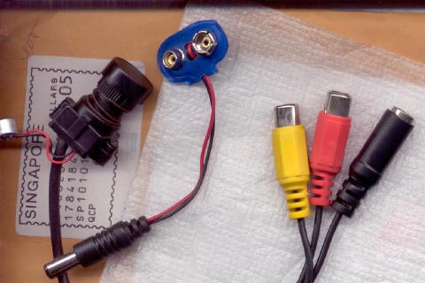
| This is
too much work for you and you want a simpler solution. Well 9 volt cmos
cameras can be bought quite reasonably on eBay. I bought one color
several years ago for $5 plus S&H from Singapore. Secure the camera
to the forward bulkhead using 5 minute epoxy and attach the battery
with a clip, this you can buy at Radio Shack. |
|
The
cameras usually
have two RCA jacks unless they are intended for
surveylance. The yellow jack is most often the video, but sometimes
they may be white. Cut off the jack and strip 1/4 inch off the end
exposing the wire do same to umbilical cord, pick the red for video,
and use the black for the antenna.
Slip on heat shrinking tubing onto the wire and solder exposed wires,
slide the heat shrinking tubing over the bare wire and apply heat.
The antenna wire (black) can be sodered right onto the reciever in most
cases. or simply cut the ariel whip short and solder it to the
umbilical.
|
|
|
|
|
Sealing the umbilical/
antenna
|

 |
| List of
manufacturers suplliers: |
Acrylic
domes:
UK
http://www.applegate.co.uk/company/09/12/260.htm?clickedfrom=HOTLINK_29648
USA
http://www.321cam.com/videosolutions/SurveillanceDomes.htm
$30 domes
http://www.globalplastics.ca/micro.htm
ABS PIPE
http://www.charlottepipe.com/Default.aspx?Page=ABSPVCDWV&type=ABSPVCDWV
Marine
Hardware
Ballast tanks
http://www.mikessubworks.com
http://www.rcboats.com
http://www.dumasproducts.com
Dumas
#3003 1/8 shaft 1.75"
dia Nylon Prop
Dumas
#2603 Stainless Steel Shaft
+ stuffing box
Dumas
#2008 1/8 x 1/8 Shaft Coupling
For phone orders call 1-800-458-2828 toll
free
|
Each
$1.20
$6.00
$6.25
|
#2008
 |
#2603
 |
#3003
 |
Electric
Motors
http://www.jameco.com
|
Download
the entire ebook here ROV
Plans
Plus bonus plans not shown here.
|
|
|